![]()
![]()
|
|
|
![]() Module(s): Basic: Walls, Openings, Components module
Module(s): Basic: Walls, Openings, Components module
Every wall, beam and upstand you draw has a component axis. This is a reference line that is used when the component is entered. The axis of a straight wall is simply the line you enter. In the case of a curved wall it is the arc, with a spline-based wall the spline, with an entity-based wall it is the donor entity.
You can define the position of the axis within the component in the ![]() Properties of the relevant component; consequently the resulting directions of extension vary.
Properties of the relevant component; consequently the resulting directions of extension vary.
The component axis contains all the information that is required for creating the component in question. You can define whether and how the component axis is displayed in the ![]() Properties of the relevant component, Format properties tab,
Properties of the relevant component, Format properties tab, ![]() Settings for component axis or in the
Settings for component axis or in the ![]() Options - Components page - Component axis area.
Options - Components page - Component axis area.
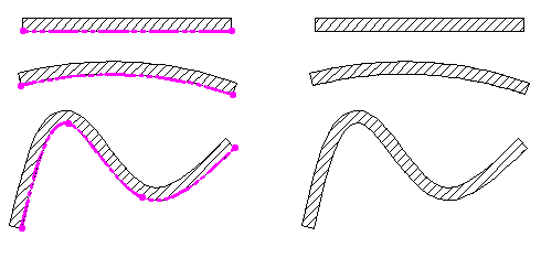
Figure: wall with/without component axis displayed
Modification options
When modifying components like walls, beams and upstands, however, the component axis has many advantages.
The section that follows provides an overview of modification tools and the benefits provided by the component axis in each case. All these additional tools can only be utilized with components that were created with an axis.
Architecture-specific modification tools
|
|
Features when modifying architectural elements |
|
You can change the position of the axis in the component and/or the component setup (single-tier/multi-tier). Changing the position of the axis within the component does not affect the geometry of the component. |
|
|
Each of the new components is given a separate component axis. The position of the axis and its direction of extension are the same for both linear components. |
|
|
When a linear component is joined with a second linear component, the component axis adapts to the new outline. |
|
|
When a linear component is joined with a line, the component axis adapts to the new outline. |
|
|
When modifying the exterior wall, most architectural components are detected and taken into account for the altered wall. |
|
|
You can use this tool to modify openings and walls in a document in a single step. After clicking a donor component, the parameters are transferred and the Properties dialog box of the clicked component is displayed. Confirm the Properties dialog box. You can then select any number of components of the same type in the drawing file – for example, all doors, or all openings, or all niches. After confirming again, all the active components are modified in accordance with the settings in the Properties dialog box. You can also change the position of the axis in the component and/or the component setup (single-tier/multi-tier). |
Tools for making geometric modifications
When you modify the geometry of a wall with the tools that are familiar to you from 2D drafting, whether the component axis is displayed or not makes a difference:
|
|
Features when modifying architectural elements |
|
With component axis displayed: Without component axis displayed: |
|
|
With component axis displayed: Without component axis displayed: |
|
|
With component axis displayed: Without component axis displayed: |
| (C) Allplan GmbH | Privacy policy |