![]() Tool(s): Wall + Downstand Beam, Upstand Beam + Upstand + Strip Foundation + Profile Wall
Tool(s): Wall + Downstand Beam, Upstand Beam + Upstand + Strip Foundation + Profile Wall
You can use ![]() Polygonal Component (Inscribed) to draw polygonal components (walls) based on the radius of an inscribed circle. Polygonal components are entered in the same way as curved components. You can define the number of straight sections that go to make up the component in the Properties dialog box.
Polygonal Component (Inscribed) to draw polygonal components (walls) based on the radius of an inscribed circle. Polygonal components are entered in the same way as curved components. You can define the number of straight sections that go to make up the component in the Properties dialog box.
Inscribed means that the component is based on the radius of an imaginary, inscribed circle. They are counted as partial sections. The division is at a tangent to the circle that you entered when defining the geometric outline.
Difference between inscribed and circumscribed polygonal components
Schematic overview of curved and polygonal walls
To create an inscribed polygonal component
The secant is displayed.
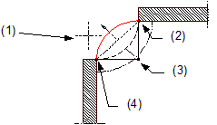
(1) Direction in which the arc is to extend – relative to the secant
(2) Connecting point = end point of component
(3) Center point
(4) Connecting point = start point of component
The position of the component axis and its direction of extension are displayed in the preview. In the case of components with multiple construction layers (e.g. walls), you can see the component setup and the thickness of the various layers. The position of the fist layer is identified by the number 1, which is displayed in the color associated with the component axis.
You can change this setting at any time while entering components.
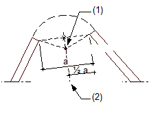
(1) Center of circle
(2) Perpendicular bisector
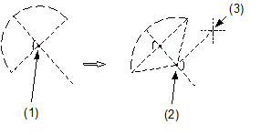
(1) Proposed center of circle
(2) New center of circle
(3) Crosshairs
The polygonal component is drawn.
| (C) Allplan GmbH | Privacy policy |
