The following example shows how to create flat text and sculptured text.
- On the Create menu, click Text, and then click
 Horizontal Text (How).
 - Place the start point of the text.
- Select a font in the dialog box and define the text parameters.
Tip: It is best if you use a TrueType font, e.g. Times New Roman.
- Enter the text ('Hotel' in this example) and click OK to confirm.
- To convert the text to 2D lines, click
 Hidden Line Image, Wireframe on the Default toolbar and then select Wireframe.
 - Now you can specify whether construction lines (if any) are also to be converted to a wireframe model. Choose Yes or No at the following prompt asking whether you want to include construction lines.
The wireframe model of the text is displayed in a separate window.
- Close the window, click Yes at the following prompt asking whether you want to save the wireframe model.
- The Select destination drawing file dialog box is displayed. Select a drawing file where the wireframe model is to be saved and then click OK to confirm.
- Close the drawing file with the text and open the drawing file with the wireframe model. The difference is immediately evident: Only the outline of the text is displayed.

Tip: For the steps that follow, go to the Window menu and click  3 Viewports.
- On the Create menu, click Architecture and then Special: Walls, Openings, Components. Click
 Freeform Wall.
 - Set the height of the wall so that its bottom level is flush with the lower default reference plane and set the height of the wall to 10 cm – also based on the lower reference plane.

- The converted text is "hollow"; it consists of connected lines and polygons. Enter the outline of the freeform walls using the polyline entry tools.
- Select
 Area detection.
 - In the Input Options, click
 Single and then
  Island detection. Closed outlines within an area are detected and cut out automatically.
 - Click in the outline of the character. When dealing with the letters 'o' and 'e', make sure that you do not click in the area that is to be cut out.
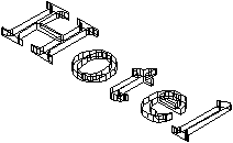
The outlines of the closed polyline and of the 'island' are detected automatically and the freeform wall is created.
The text is three-dimensional and still attached to the reference planes. This means that it cannot be freely rotated. To detach it, convert it to a 3D entity.
- On the Create toolbar, point to Bonus Tools and 3D Modeling. Click
 Convert Elements. Set the Conversion Mode to Architecture to 3D solids.
Note: The freeform walls are converted in the current document.
- Select the architectural solids.
The hatching (or pattern or fill) of the architectural elements disappears in plan view; this indicates that they have been converted to 3D.
As the text is now a 3D entity you can now edit it using the tools in the 3D Modeling module.
- To create a text that you might put on a façade, go to the Change menu and point to Bonus Tools and 3D Modeling. Click
 Rotate 3D Elements.
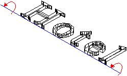
- Select the text. To define the axis of rotation, click (in isometric view, for example) on the text's start and end points. Enter 90 degrees of the angle of rotation.
- Delete the wireframe model of the text that is still visible in the plan view.
