![]()
![]()
|
|
|
![]() Module(s): Dimension Lines
Module(s): Dimension Lines
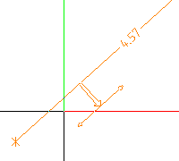
You can use the ![]() Automatic Elevation Dimensioning tool to automatically dimension the elevation of existing architectural components. Draw a line through the components. The points at which the line and the components intersect are automatically dimensioned.
Automatic Elevation Dimensioning tool to automatically dimension the elevation of existing architectural components. Draw a line through the components. The points at which the line and the components intersect are automatically dimensioned.
To dimension elevation points automatically
The dimension line is displayed on-screen. The reference points are placed on the points where the clipping line and the dimensioned element intersect.
To produce a dimension line with extension lines, the Extension lines option in the Dimension Line Settings dialog box must be enabled.
Note: The clipping line is always parallel or perpendicular to the dimension line.
| (C) Allplan GmbH | Privacy policy |